- 您现在的位置:买卖IC网 > Sheet目录2001 > ISL12022MIBZR5421 (Intersil)IC RTC/CALENDAR TEMP SNSR 20SOIC
1
Low Power RTC with Battery Backed SRAM, Integrated
±5ppm Temperature Compensation and Auto Daylight
Saving
ISL12022MR5421
The ISL12022MR5421 device is a low power real time clock
(RTC) with an embedded temperature sensor and crystal.
Device functions include oscillator compensation,
clock/calendar, power fail and low battery monitors, brownout
indicator, one-time, periodic or polled alarms, intelligent
battery backup switching, Battery Reseal function and 128
bytes of battery-backed user SRAM. The device is offered in a
20 Ld SOIC module that contains the RTC and an embedded
32.768kHz quartz crystal. The calibrated oscillator provides
less than ±5ppm drift over the full -40°C to +85°C
temperature range.
The RTC tracks time with separate registers for hours, minutes,
and seconds. The calendar registers track date, month, year
and day of the week and are accurate through 2099, with
automatic leap year correction.
Daylight Savings time adjustment is done automatically, using
parameters entered by the user. Power fail and battery
monitors offer user-selectable trip levels. The time stamp
function records the time and date of switchover from VDD to
VBAT power, and also from VBAT to VDD power.
The ISL12022MR5421 has redesign package to increase
Contact and Air Discharge ESD performance.
Related Literature
See AN1549 “Addressing Power Issues in Real Time Clock
Applications”
Features
Embedded 32.768kHz Quartz Crystal in the Package
20 Ld SOIC Package (for DFN version, refer to the
ISL12020M)
Calendar
On-chip Oscillator Temperature Compensation
10-bit Digital Temperature Sensor Output
15 Selectable Frequency Outputs
Interrupt for Alarm or 15 Selectable Frequency Outputs
Automatic Backup to Battery or Supercapacitor
VDD and Battery Status Monitors
Battery Reseal Function to Extend Battery Shelf Life
Power Status Brownout Monitor
Time Stamp for Battery Switchover
128 Bytes Battery-Backed User SRAM
I2C-Bus
RoHS Compliant
Applications
Utility Meters
POS Equipment
Printers and Copiers
Digital Cameras
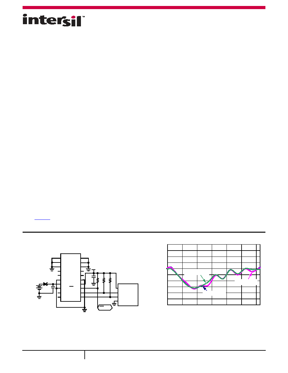
FIGURE 1. TYPICAL APPLICATION CIRCUIT
FIGURE 2. PERFORMANCE CURVE
GND
NC
GND
NC
GND
NC
VBAT
VDD
GND IRQ/FOUT
NC
SCL
SDA
ISL12022MR5421
1
2
3
4
5
6
7
8
9
10
20
19
18
17
16
15
14
13
12
11
SCHOTTKY DIODE
BAT54
BATTERY
3.0V
3.3V
C2
0.1F
C1
0.1F
R1
10k
R2
10k
R3
10k
VDO
SCL
SDA
GND
MCU
INTERFACE
IRQ/FOUT
-5
-4
-3
-2
-1
0
1
2
3
4
5
-40
-20
0
20
406080
TEMPERATURE (°C)
F
OU
T
FRE
Q
UENCY
ERROR
(ppm
)
VDD = 2.7V
VBAT = 5.5V
VDD = 3.3V
OSCILLATOR ERROR vs TEMPERATURE
CAUTION: These devices are sensitive to electrostatic discharge; follow proper IC Handling Procedures.
1-888-INTERSIL or 1-888-468-3774
|Copyright Intersil Americas Inc. 2010-2012. All Rights Reserved
Intersil (and design) is a trademark owned by Intersil Corporation or one of its subsidiaries.
All other trademarks mentioned are the property of their respective owners.
June 7, 2012
FN7576.3
发布紧急采购,3分钟左右您将得到回复。
相关PDF资料
ISL12023IVZ
IC RTC/CLDR TEMP SNSR 14-TSSOP
ISL12024IRTCZ
IC RTC/CALENDER 64BIT 8-TDFN
ISL12024IVZ
IC RTC/CALENDAR EEPROM 8-TSSOP
ISL12025IVZ
IC RTC/CALENDAR EEPROM 8-TSSOP
ISL12026IBZ-T7A
IC RTC/CALENDAR EEPROM 8SOIC
ISL12027IV27AZ
IC RTC/CALENDAR EEPROM 8-TSSOP
ISL12028IVZ
IC RTC/CALENDAR EEPROM 14-TSSOP
ISL12029IVZ
IC RTC/CALENDAR EEPROM 14-TSSOP
相关代理商/技术参数
ISL12022MIBZ-T
功能描述:实时时钟 REAL TIME CLK & TEMP COMPENSATED CRYSTAL RoHS:否 制造商:Microchip Technology 功能:Clock, Calendar. Alarm RTC 总线接口:I2C 日期格式:DW:DM:M:Y 时间格式:HH:MM:SS RTC 存储容量:64 B 电源电压-最大:5.5 V 电源电压-最小:1.8 V 最大工作温度:+ 85 C 最小工作温度: 安装风格:Through Hole 封装 / 箱体:PDIP-8 封装:Tube
ISL12022MIBZ-T7A
功能描述:IC RTC/CALENDAR TEMP SNSR 20SOIC RoHS:否 类别:集成电路 (IC) >> 时钟/计时 - 实时时钟 系列:- 产品培训模块:Obsolescence Mitigation Program 标准包装:1 系列:- 类型:时钟/日历 特点:警报器,闰年,SRAM 存储容量:- 时间格式:HH:MM:SS(12/24 小时) 数据格式:YY-MM-DD-dd 接口:SPI 电源电压:2 V ~ 5.5 V 电压 - 电源,电池:- 工作温度:-40°C ~ 85°C 安装类型:表面贴装 封装/外壳:8-WDFN 裸露焊盘 供应商设备封装:8-TDFN EP 包装:管件
ISL12022MIBZ-TR5421
功能描述:实时时钟 REAL TIME CLK W/MFK IMPROVED ESD AIR RoHS:否 制造商:Microchip Technology 功能:Clock, Calendar. Alarm RTC 总线接口:I2C 日期格式:DW:DM:M:Y 时间格式:HH:MM:SS RTC 存储容量:64 B 电源电压-最大:5.5 V 电源电压-最小:1.8 V 最大工作温度:+ 85 C 最小工作温度: 安装风格:Through Hole 封装 / 箱体:PDIP-8 封装:Tube
ISL12022MR5421
制造商:INTERSIL 制造商全称:Intersil Corporation 功能描述:Low Power RTC with Battery Backed SRAM, Integrated 5ppm
ISL12022M-R5421
制造商:INTERSIL 制造商全称:Intersil Corporation 功能描述:High-Accuracy RTC Modules, Feature-Rich RTCs
ISL12023
制造商:INTERSIL 制造商全称:Intersil Corporation 功能描述:Low Power RTC with Battery-Backed SRAM and Embedded Temp Compensation ±5ppm with Auto Daylight Saving
ISL12023IVZ
功能描述:实时时钟 REAL TIME CLK/CLNDR W/TEMP COM 14 L RoHS:否 制造商:Microchip Technology 功能:Clock, Calendar. Alarm RTC 总线接口:I2C 日期格式:DW:DM:M:Y 时间格式:HH:MM:SS RTC 存储容量:64 B 电源电压-最大:5.5 V 电源电压-最小:1.8 V 最大工作温度:+ 85 C 最小工作温度: 安装风格:Through Hole 封装 / 箱体:PDIP-8 封装:Tube
ISL12023IVZ-T
功能描述:实时时钟 REAL TIME CLK/CLNDR W/TEMP COM 14 L RoHS:否 制造商:Microchip Technology 功能:Clock, Calendar. Alarm RTC 总线接口:I2C 日期格式:DW:DM:M:Y 时间格式:HH:MM:SS RTC 存储容量:64 B 电源电压-最大:5.5 V 电源电压-最小:1.8 V 最大工作温度:+ 85 C 最小工作温度: 安装风格:Through Hole 封装 / 箱体:PDIP-8 封装:Tube